Description: The following description explains the process of feature extraction with quality assurance (QA) being part of a reliable feature extraction.
Description of Screening: The microaray image screening algorithm in GridFeatures performs four types of quality assurance (QA) screenings in order to eliminate grid cells with unreliable microarray information. It is assumed that a grid of cirular dots has been detected with the GridLine tool or with any other tool that reports a set of intersecting lines in a GridLineResult data structure. Screening of a microarray image is conducted either globally with data statistics computed over the whole image or locally with statistical analysis of each grid cell.
The global screening eliminates grid cells that contain sample mean intensity in all bands of the foreground area (signal or dot area) smaller than the sample mean intensity of the background plus three standard deviations computed from the overall background.
The local screening is based on (1) location and size, (2) signal to noise ratio (SNR), (3) topology of signal area and (4) statistical models of the signal intensities. The goal of local screening is to eliminate grid cells with (1) circular signal area outside of allowed location and radius deviations, (2) small signal with respect to background, (3) disconnected signal areas and (4) inconsistent intensity probability distributions.
If one does not select any screening then all grid cells are considered to be valid with a circular area (dot) of the radius defined by "DotRadius" input value and a center location defined by the center of a grid cell. Any invalid grid cell detected by one or several screening types will be eliminated by removing any signal area from the grid cell. Thus, the output of the screening is a mask image with present or absent signal areas.
Location and size type of local screening is designed to eliminate grid cells that do not satisfy DotRadius +/- DeltaDotRadius requirement where the location of a dot is computed based on local statistics over a binary grid cell mask obtained by thresholding. The type of thresholding (MaskType) is also a variable and is described in the Threholding tool documentation of Image To Knowledge (I2K) software package.
Signal to noise (SNR) type of local screening serves the purpose of eliminating any grid cells where the difference between the sample mean over a signal area and the sample mean over a non-signal area is less than a value defined by MinContrast.
Local screening using topology is based on performing connectivity analysis inside of each grid cell and eliminating those grid cells that contain the largest connected signal area outside of the interval [DotArea*(1-DevTopologySize), DotArea*(1+DevTopologySize)], where DotArea is computed as DotArea=Pi*DotRadius^2.
Local screening using statistical probability distribution function (PDF) models investigates statistical intensity distributions over a signal area in each grid cell. A grid cell is eliminated if the PDF mmodel does not match a selected distribution type (DistType). A user can choose one out of nine PDF models and view a histogram of PDF models computed over all grid cells.
Setup of Screening Tool: The basic set of parameters for running the GridFeatures screening algorithm consists of the following input variables:
DotRadius is the expected dot radius.
MaskType defines the type of thresholding used by location and size type of screening and by topology based screening.
DeltaDotRadius is the maximum allowed deviation in radius from the value of DotRadius. This value is used by location and size type of screening.
MinContrast is the minimum contrast between the signal and background sample means inside of a grid cell in order to pass the SNR based screening.
DevTopologySize defines the amount of allowed deviation in size from the expected dot area. The expected dot size is computed as DotArea=Pi*DotRadius^2 and the range of acceptable sizes is [DotArea*(1-DevTopologySize), DotArea*(1+DevTopologySize)]. The value of DevTopologySize should be in the interval [0,1] and is used when Topology based screening is on.
DisType defines the expected PDF model of the intensity distribution over a signal area. This selection is used by Statistical type of screening.
These input parameters can be set in the GridLineFeatDialog under tab dialog "Screen" (see below). Any selection of a screening type is accomplished by checking a check box; Loc:Size - location and size based screening, SNR - signal to noise ratio based screening, Topology - topology based screening and Statistics - statistical PDF model based screening.
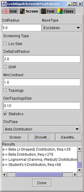
Run: After all the input parameters were set according to their description, a user clicks on button "Screen" to execute selected screenings. The status of the execution is displayed in in the text area labeled as Results. If no screening type has been selected then the resulting mask is formed based on DotRadius and input grid information.
Results: The result of any screening is a mask image that can be viewed by clicking on "ShowMask". During the "ShowMask" operation one can view other resulting information about the screening, for example, a number of valid dots (grid cells), an average dot radius or a histogram of PDF models if the "Statistics" check box is marked. It is also possible to save the mask image for later use by clicking "SaveMask".
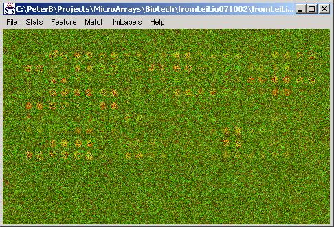
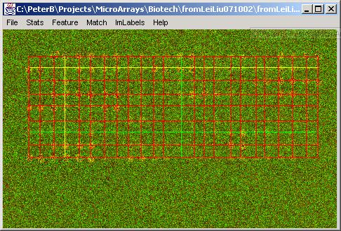
Example results are presented below. First, the grid alignment is performed and the original image and the resulting grid are shown.
Second, a screening type is selected and the figures below show results obtained by running each type of screening.
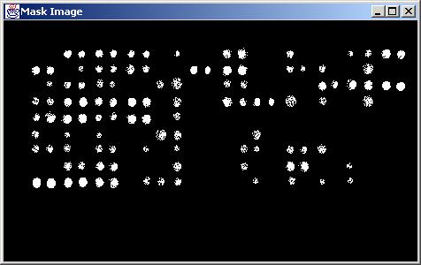
Results obtained without any screening (DotRadius = 5.0).
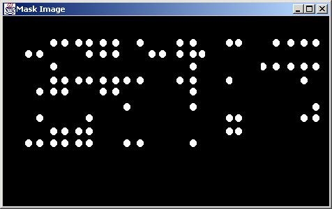
Results obtained with "Loc:Size" (location and size) screening type (DotRadius = 5.0, DeltaDotRadius = 2.0, MaskType = Euclidean).
Results obtained with "SNR" (signal to noise ratio) screening type (MinContrast = 1.0).
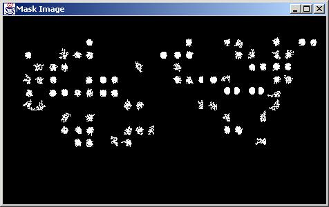
Results obtained with "Topology" screening type (DevTopologySize = 0.15, MaskType=Euclidean).
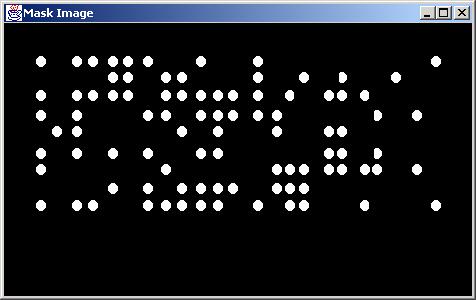
Results obtained with "Statistics" (PDF models) screening type (DistType = Beta Distribution).
Description of Feature Extraction: Once selected quality assurance (QA) control methods (screening types) have been applied, a user can extract features for data mining from original microarray images over a mask generated by screening process. The feature extraction algorithm computes features per each grid cell based on foreground (signal) and background statistics inside a grid cell. If a grid cell does not contain any signal area (white in the mask image) then all selected features for that grid cell are set to a unique value representing an invalid cell (unreliable information).
Setup of Feature Extraction Tool: The set of currently suported features is described next.
Mean is the sample mean in each channel (for example, red and green) at each grid cell over the signal area defined by a corresponding location in the mask.
Stdev is the estimated standard deviation in each channel (for example, red and green) at each grid cell over the signal area defined by a corresponding location in the mask.
Skew is the estimated skew in each channel (for example, red and green) at each grid cell over the signal area defined by a corresponding location in the mask.
Kurtosis is the estimated kurtosis in each channel (for example, red and green) at each grid cell over the signal area defined by a corresponding location in the mask.
MeanRatio is the ratio of sample mean values in red and green channels.
LogMeanRatio is the natural logarithm of the ratio of sample mean values in red and green channels.
Any selection of features is performed by marking a check box in the GridLineFeatDialog under tab dialog "Feat" (see below). Each label next to a check box denotes one of the described features; Mean, Stdev, Skew, Kurtosis, MeanRatio and LogMeanRatio.
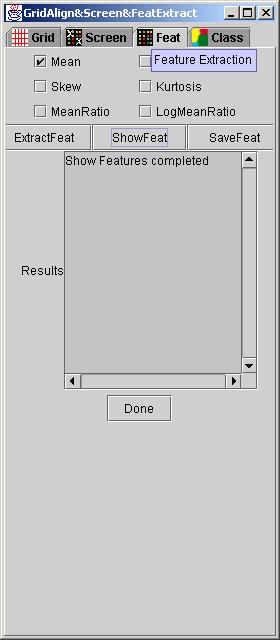
Run: Once features have been selected, a user clicks on button "ExtractFeat" to execute feature extraction. The status of the execution is displayed in in the text area labeled as Results. The result of any feature extraction is a feature image. The extracted features create a grid-based information since the microarray dots form a grid pattern. Thus, it is natural to extract features and maintain the grid in a form of a feature image. Each extracted feature forms a point in the feature image which is then used for classification.
Results: The result of any feature extraction is a feature image that can be viewed by clicking on "ShowFeat". It is also possible to save the feature image for later use by clicking "SaveFeat".
Example results are presented below.
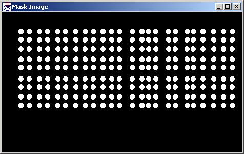
Original image and mask image used by feature extraction algorithm.
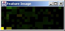
The feature image above represents sample mean values extracted at each grid cell from red and green channels and combined into a pseudo-color feature image.