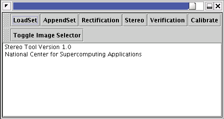
Figure 1: Main Window
Computational stereopsis is the technique of using computers to extract depth from multiple images (similar to what your eyes do). The Computational Stereopsis tool solves a subset of the most general formulation. Specifically, given two images of a scene with considerable overlap and purely horizontal displacements, it will extract a scaled depth map valid over "matched" portions of the image. The depth map can then be calibrated by bringing in external [depth] information.
To accomodate images taken without aligned cameras (i.e. image pairs without purely horizontal displacements), the Computational Stereopsis tool provides an implementation of a "stereo rectification" algorithm. This algorithm takes a reference image and unrectified image as input, prompts the user to identify a set of matching points, and returns a rectified version of the second image: a [perspective] warped image with purely horizontal displacements from the reference image.
For more information on Computational Stereopsis, including "real-world" issues, reference:
M.Z. Brown, D. Burschka, and G.D. Hager, "Advances in Computational Stereo," IEEE Trans. on Pattern Analysis and Machine Intelligence (PAMI), Vol. 25, No. 8, pp. 993-1008, 2003.
For detailed information on the basic algorithm used for performing the stereopsis, reference:
H. Hirschnuller, "Improvements in Real-Time Correlation-Based Stereo Vision," Proc. IEEE Workshop on Stereo and Multi-Baseline Vision, Kauai, Hawaii, pp. 141-148, 2001.
For information on the stereo rectification algorithm, reference:
F. Isgro and E. Trucco, "Projective Rectification without Epipolar Geometry," Computer Vision and Pattern Recognition (CVPR), Vol. 1, pp 94-99, 1999.
The computational stereopsis tool (StereoFrame) can be started using the "Stereo" option of the I2K "Customs" menu. When you select this option, a new window will open on the screen (Figure 1).
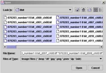
StereoFrame can load multiple images for image selection and comparison. Clicking the "LoadSet" or "AppendSet" buttons launches a new file selection window titled "Open". In the Open window, a user may load multiple images by holding "Shift" or "Ctrl" key. Using the "LoadSet" button loads multiple images and discards all existing images in the Thumbnail viewer. A user can preserve all existing image in the Thumbnail viewer and append new images by clicking the "AppendSet" button. Figure 2 shows an "Open" window.
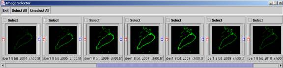
After loading images, the Thumbnail window will appear for image browsing and selection. Figure 3 shows the Thumbnail viewer. By moving the scroll bar on the bottom of the viewer window, a user can browse the images and check the filenames for each image. The "Select" checkbox above each image is for selecting some particular images for image processing (Rectification, Stereo, and Comparison).
By clicking the "Rectification" button in the main window, one can launch the Stereo Rectification Tool (see Figure 4). The Stereo Rectification Tool window consists of two panels: "Stereo Rectification" and "Rectification Parameters". The "Stereo Rectification" panel contains buttons for computing; loading and saving rectification parameters, and image transformation using the computed (or loaded) parameters. The "Rectification Parameters" window shows the values of computed or loaded perspective transformation parameters. The "Send to Main" button will load the selected image to the "Image to Knowledge" Software.
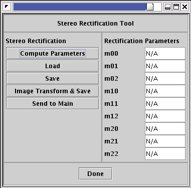
In the Rectification Parameters panel, nine values define the perspective transformation model in row-major order. The numbers at the end of the parameter name are the subscripts in the [3x3] transformation matrix.
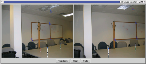
By clicking the "Compute Parameters" button in the Stereo Rectification Tool window, one can launch the Feature Selector window for selecting transformation control points. Figure 5 shows the GUI of the Feature Selector window. The Feature Selector window displays two images before their rectification, for instance, two images of a scene from slightly differing views. A user should select approximately 15 matching pairs of control points in both images to compute the perspective transformation parameters successfully. Each selected point is displayed as a colored circle with the index of the pair. Clicking "Transform" will use the selected control points to calculate the parameters used for stereo rectification.
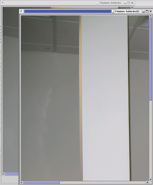
Note: The Feature Selector window size is optimized for 1280 by 1024 monitor resolution. For big images that do not fit in the current monitor, the software automatically detects the screen resolution and launches two scrollable windows: one for each image (Figure 6).
Once the perspective transformation parameters are determined, a set of images can be transformed and saved by selecting an image and clicking the "Image Transform & Save" button. A user can specify the suffix of the transformed saved images.
To perform stereopsis, simply pick two [rectified] images and select the "Stereo" button in the StereoFrame window (Figure 1). The Stereopsis calculation can take a long time. After the computation has completed, the [uncalibrated] depth map will appear in the main I2K window.
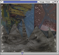
By selecting two images in the Thumbnail window followed by clicking the "Verification" button in the main window, one can compare two images. Figure 7 shows the Image Composition window comparing a [saved] depth map to the "left" image of a stereo pair.
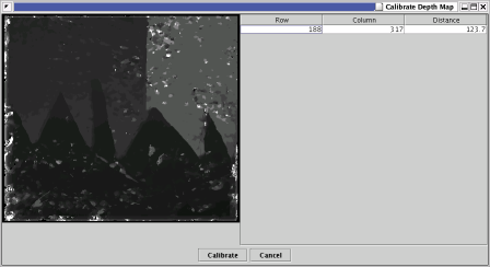
To calibrate a depth map, ensure that the depth map is loaded in the main "Image to Knowledge" window (the default location of a computed depth map). Click the "Calibrate" button in the StereoFrame window to bring up the window in Figure 8. To calibrate the image, click a pixel corresponding to a point of known scene depth: you will be prompted for the depth in meters. You can repeat this process for multiple pixels in an attempt to improve the calibration. When done, click the "Calibrate" button at the bottom of the window shown in Figure 8: the depth map will be calibrated in-place.
In many cases, the points of known depth may be difficult to "pick out" from the depth map. Another image corresponding to the "left stereo" image (or the "left stereo" image itself) can be used instead by selecting the image from the "Thumbnails" image selection window before clicking the "Calibrate" button in the StereoFrame window. The rest of the calibration procedure is as before.