Simulations of Image Registration Using Rigid and Affine Transformations:
Registration and Cross Section Alignment Tool
David Clutter, Sang-Chul Lee and Peter Bajcsy
Introduction
This tool is designed to simulate image registration using rigid and affine transformation models. The goal is to understand image registration decisions when it comes to choosing registration transformations. Furthermore, one can better assess the impact of a chosen registration transformation on image alignment accuracy by simulating distribution and size of matching image feature, as well as transformation parameters.
Instructions
This tool is designed to simulate image registration using rigid and affine transformation.
Click START to launch the tool in a new window.
First, specify the number of features that will be used for establishing the transformation parameters. In this simulation code, the features are disks of variable radii. The centroid locations of disks form the input to the algorithm that estimates transformation parameters. The number of features should not be less than three otherwise the parameters cannot be estimated.
Second, click the Start button. A new simulation window will appear as shown in Figure 1. The red disks correspond to features that have to be transformed to the coordinate system of the blue disks. The indices on top of red and blue disks define the pair-wise feature correspondence. If a user chose more than four features then the disks with indices larger than four will be stacked on top of the disk labeled with the index 3.
Third, move the red and blue disks around to simulate various registration scenarios. Red disks can be moved by clicking the left mouse on the disk area and dragging it. Blue disks can be moved by clicking the right mouse on the disk area and dragging it. The location of disks can be also set in the Interactive Input panel (see Figure 1). The tabs Target Image (or blue disks) and Transforming Image (red disks) should be used for setting the appropriate coordinate values. The Interactive Input panel contains also entries for changing background color intensity for each disk interior, foreground color intensity for each disk rim, and disk radius.

Figure 1. Simulation window.
Fourth, click the Update and
Transform buttons to:
(a) update all information from the Control Panel,
(b) estimate transformation parameters and
(c) generate the transformed image in the right upper corner.
The transformation parameters and the transformation errors associated with the displayed image are shown in the
Result area (lower right corner).
By default, an affine registration transformation is used as indicated by the check box in the Options panel.
By un-checking the affine transformation, a rigid transformation model will be used. After updating any entries in the
Control Panel, new results can be generated
by clicking the Update and Transform buttons.
Examples
- Alignment Tool 1 - Cross sections of blood vessels.
- Alignment Tool 2 - Image Size Selection.
Cross sections of blood vessels
Let us assume that the goal is to understand and evaluate the accuracy of image alignment, where the images are obtained from fluorescent confocal laser scanning microscope (CLSM) and the imaged medical structures are cross sections of blood vessels. In this case, one can obtain registration results using the simulation software for two or more cylinders that would model blood vessel cross sections. These simulation experiments would verify alignment results for 3D volume reconstruction and reveal any unexpected alignment errors in a 3D volume obtained from measured data.
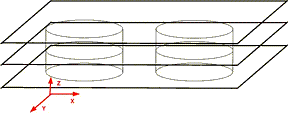
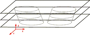
Figure 2. (a) Cross sections of two straight cylinders. (b) Cross sections of two cylinders slanted in the (z,x) plane.
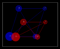
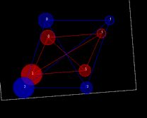
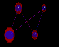
Figure 3. Cross sections of four cylinders (left) slanted along z-axis with consistent scale and shear. The visualization is in (x,y) plane with blue and red color denoting different cross sections. Simulation results obtained using rigid (middle) and affine (right) transformations.
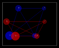
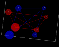
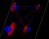
Figure 4. Cross sections of four cylinders slanted along z-axis without consistent scale or shear (left). The visualization is in (x,y) plane with blue and red color denoting different cross sections. Simulation results obtained using rigid (middle) and affine (right) transformations that are considered as a registration failure based on the residual error.
Simulations with Background Images
We have updated the tool with an option that allows a user to upload two background images. The images can be uploaded by clicking on the additional bottom labeled as Open Background Images (see Figure 5). Simulations with background images provide a mechanism for placing the disks of appropriate size at locations corresponding to measured data. One can then observe how well a rigid or affine transformation aligns the two images and how well the local distortions of the disks match the distortions of measured features.

Figure 5 illustrates different setups for visual inspection of the results. A screen capture of the tool with two background images that have to be registered.

Figure 6. Visualization of the image being transformed before (left) and after (right) an affine transformation (see the check boxes and the slider bar positions).

Figure 7. Similar visualization to what is shown in Figure 6 but the disks are shown for both images (the check box target image is checked and the left slider bar is in the right position showing only the second image).


